A generator is a machine which convert mechanical energy into electrical energy. In fact the mechanical energy is given to the armature for rotating in a magnetic field and an emf is produced in that armature. The following are the three requirements which is badly essential for a DC generator.
- Conductor
- Magnetic field
- Mechanical energy (for rotation of armature)
CONDUCTOR:- Insulated conductors are placed in armature slots.
MAGNETIC FIELD:- The magnetic field is obtained by using two ways like either permanent magnet or an electromagnet. Basically in all generator electromagnet is used and the reason behind is that, the electromagnetic field is easily controlled. These magnetic field is obtained in the pole shoe of the generator.
MECHANICAL ENERGY:- We need mechanical energy for rotation of the armature conductor and it can be obtained from the prime mover. We can get it by using water turbine, steam turbine, diesel engine turbine.
WORKING PRINCIPLE OF DC GENERATOR
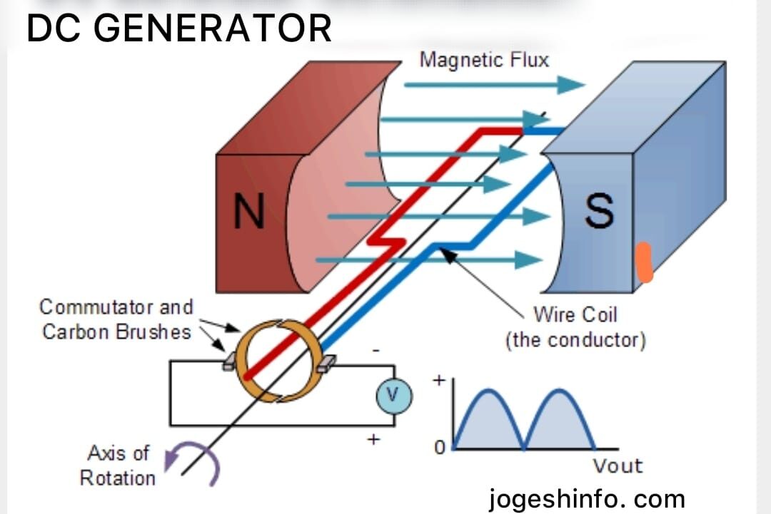
A generator works on the principle of “Faraday’s law of electromagnetic induction”. It states that, whenever a conductor is moved in the magnetic filed, an emf is generated in the conductors and the magnitude of the induced emf is directly proportional to the rate of cutting the flux.
The emf generated in the conductor is actually alternating in nature but one commutator converts the alternating current into the direct current and the carbon brush collect the direct current and make it available in the external circuit. A dc generator can also be known as dynamo.
FLEMING’S RIGHT HAND RULE
If the thumb, fore finger and middle finger of right hand stretched perpendicular to each other, then thumb will indicate the direction of motion of the conductor, fore finger will point the direction of magnetic lines of force and the middle finger will points the direction of induced emf.
PARTS OF DC GENERATOR
YOKE-It is also known as body of the machine. The field poles are mounted in it. The main function of the yoke is to provide support to the armature and filed winding. It is also provide a close path for flowing of magnetic line of forces. It is made of cast iron or silicon steel.
FIELD POLE:- The pole shoes are screwed with yoke. They are made of cast steel or cast iron as it offers low reluctance to the magnetic line of forces. All the field coils are connected in series (when it is four or six) in such a way as to produce opposite polarities at the adjacent poles. The functions of these poles are to support the field coils and to produce magnetic field in the machine.
The field poles are always electromagnet but in small machine permanent magnet is used. The narrow space between the pole shoe and armature is known as air gap.
ARMATURE CORE & WINDING:- The armature is a cylindrical drum consisting of thin circular stampings of silicon steel to (to reduce the hysteresis losses) and winding. The disks are insulated from each other by shellac varnish, thin paper or oxide film coating. The stamping sheets are mounted on a shaft. A commutator is fitted on one side and a cooling fan is fitted on another side. The core also provide low reluctance for the flow of line of forces. Slots are also provide in it to keep the armature winding in it’s housing.
The armature performs mainly three functions such as
- It supports the conductor.
- It causes the conductor to rotate between the magnetic field.
- It provides low reluctance.
COMMUTATOR:-
It is electrical device which automatically reverses the direction of the coil. It consist of number of copper segments of high conductivity, hard drawn copper insulated from each other as well as from the shaft of the armature. One riser is also there attached with the commutator in which armature coil ends are soldered in it.
CLASSIFICATION OF DC GENERATOR
DC generators are of two types in accordance to magnetization of field.
- Permanent magnet generator :- In this generator field flux is produced by permanent magnet. Field flux of this generator remains constant, so the emf induced in such type of generator is always remains constant.
- Electromagnet generator :- In this type of generator field flux is produced by passing the dc current through the field coils. The field coils are to be excited separately (from external dc source) or self induced emf.
Again Electro magnet generator divided into two types such as Self excited generator & separately excited generator. Again self excited generator are divided into three types like Series generator, shunt generator and compound generator. Compound generator is again divided into two types like long shunt compound generator and short shunt compound generator.
Now there is question may arisen in your mind that, how separately excited generator works?
Ans- In this type of generator the field flux is produced by using external dc source like battery or another dynamo. Then after achieving the magnetic field, the armature rotate with the help of prime mover (it may be water turbine, diesel turbine etc.)
Then how self excited generator works?
Ans-In this generator some residual magnetism is also provided in the poles. When the armature rotates under the poles, due to the residual magnetism, some emf is induced in the armature winding (very small amount). Again this small amount of emf is applied across the field winding and the current flowing in such a way that it increases more emf in the armature conductors which further increases the flux and in this way the armature produces full rated voltage within a short time. Thus in self excited generator no external source is required to excite the field winding. As self induced emf is used to excite the field winding, it is known as self excited generator.
Self excited generators are of three types such as ,
- Series Generator
- Shunt Generator
- Compound Generator
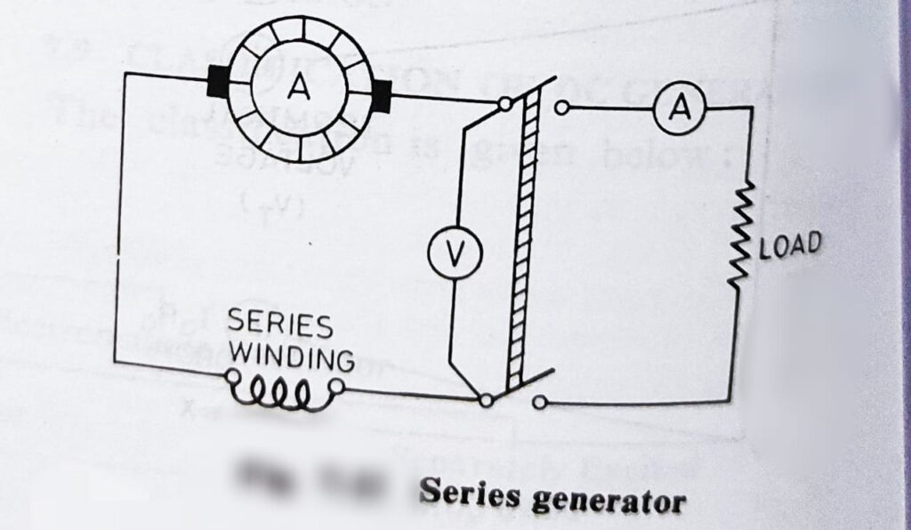
SERIES GENERATOR:-

This generators are so named as the field winding is connected in series with the armature winding. The wire used in the armature and field winding is comparatively thick and few turns. This type of generator is run at full speed and the load switch is put on. Due to residual magnetism a small emf is produced when the external load is put on and the current flow between the load, armature and field winding. As the current in the field winding increases the armature produces more emf, thus the generator build up it’s emf.
In an open circuit or in no load the generator can not build up it’s voltage as there is no flow of current is possible.
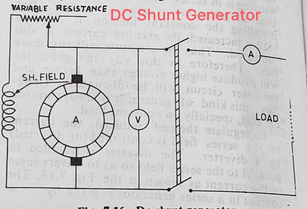
SHUNT GENERATOR

In shunt generator the field winding is connected in parallel to the armature and thus the full voltage induced in the armature is applied to the shunt field. That is why the field winding is consisting of thin wire of many turns so as to drop the full voltage across it.
When this generator is started a small amount of voltage is generated and this voltage is applied to the shunt filed which will build up more flux causes more emf to be induced in the armature and this goes on till the generator attains its full voltage. The load switch is kept open at that time of staring because the emf induced at that time is very small. If at the time of starting full load is connected in parallel to the field winding and armature, the current starts to flow in the load and not in the shunt field winding. This is because the resistance of the load is lower and current always flows through the easiest path. Thus there will not be enough current in shunt field winding and the generator will not build up voltage. This is why shunt generators are normally not started with full load.
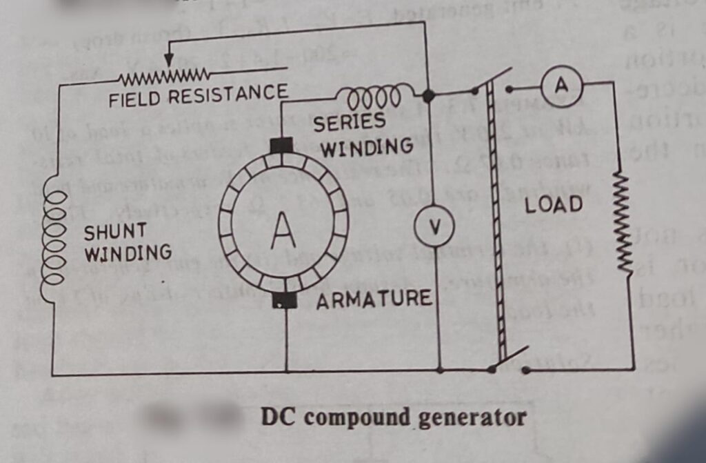
COMPOUND GENERATOR

This generators are with combination of armature, shunt field & series field winding. The shunt field is connected in parallel to the armature and designed with thin wire of many turns so as to carry full terminal voltage. The series field is designed with few turns thick wire so as to carry full load current. The key point is that both the series field and shunt field winding are mounted on the same pole shoe and electrically separated from each other.
CLASSIFICATION OF COMPOUND GENERATOR
- Short shunt compound generator.
- Long shunt compound generator.
What is armature reaction? How it could be minimized ?
It is the effect of armature flux produced due to armature current which then weakens the main magnetic flux produced due to field winding. Due to this effect there is more sparking in the carbon brushes and low terminal voltage.
It can be minimized by adopting the following ways
- The carbon brushes must be shifted to new position of MNA (Magnetic Neutral Axis)
- Some extra turns are to be winded in field winding to neutralized the flux created due to armature current.
- Some slots are made in the pole shoe to drive the main flux toward to the centre of the pole. Actually the slot increased the reluctance at the TPT (Trailing pole tip)
What is Interpoles? How they are connected in the generator?
In large machine where the load is variable to minimize the cross magnetization interpoles are used and it is connected in series with the armature winding and are placed in the middle of the main pole. The polarity of the interpoles are same as that of main poles. It strengthens the main flux produced by the main pole and thus reduces the armature reaction.
COMMUTATION:-
Changing of current direction in the armature, when passing from the influence of one pole to the next is known as commutation. Actually when any two segments of the commutator come to the contact with a brush at a time, then a short circuit is caused between two armature coil. Due to commutation a heavy sparking is seen at the brush. To minimize the commutation effect interpoles are also used.
EMF EQUATION OF THE DC GENERATOR
When the armature is rotated, the emf induced in the conductor is directly proportional to the rate of change of cutting of magnetic lines of forces.
Emf= ⱷZN X P
60 X a
Where, P=Numbers of poles.
ⱷ= Flux per pole in web.
N= Speed of armature in revolution/ Min
Z= Total number of conductors on armature.
a= Number parallel paths in armature.
E= emf produced by one of the parallel paths in volts.
VOLTAGE REGULATION OF DC GENERATOR:- In order increase or decrease the terminal voltage we can use variable resistance or rheostat or voltage regulators. In shunt generator it is connected in series with the shunt field winding but in series generator it is connected in parallel to the series field winding.
APPLICATIONS OF DC GENERATORS:-
- Series Generators- it is used for arc lighting, arc welding and booster in electrical distribution.
- Shunt Generator:- As it gives constant voltage it is used for battery charging, electroplating, lighting,
- Compound Generator:- As this generator could maintain constant voltage at different load like cranes, trams and for traction load.
LOSSES IN GENERATOR:-
Generator transforms mechanical energy into electrical energy. That means by using mechanical energy it produces electrical energy. In this conversion the amount of input mechanical energy is not same amount electrical energy output.
Input mechanical energy = Output electrical energy + Looses
THE LOOSES IN DC GENERATOR
- Copper looses
- Iron looses
- Mechanical looses
FAQs
How does a dc generator work ?
When a conductor moves in magnetic field it cuts the magnetic lines of forces and an emf is induced in that conductor. The magnitude of induced emf is directly proportional to the rate of change of cutting the magnetic lines of forces. The emf is now available at the commutator and with the help of carbon brush we can collect the emf to the external circuit.
What are the used of DC generator ?
Generally dc generators are used for battery charging, lighting, electroplating etc.
What are the 3 types of DC generators?
There are mainly three types of DC generator according to field excitation, 1. Permanent magnet generator, 2. Self excited generator, 3. Separately excited generator.
Basic principle of dc generator ?
Generally DC generator works on the principle of Faraday’s law’s of electromagnetic induction. It states that, when a conductor linkage or cuts the magnetic lines of forces an emf is produced in it and the magnitude of induced emf depend upon the rate of cutting magnetic lines of forces.


