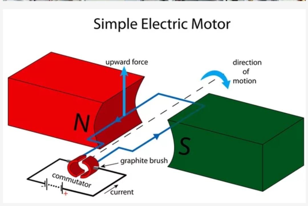
The machine which converts direct current (DC) electrical energy into mechanical energy is called direct current motor (DC Motor). The input energy which is given to the motor’s armature is Direct Current and the mechanical energy is available in the DC Motor shaft.
Working principle
When ever a current carrying conductor is placed in a magnetic filed it experiences some electromagnetic force and it tends to move. That means, here the current carrying conductor is the armature to which direct current is given through commutator and is placed in a magnetic field either it may be permanent magnetic field or electromagnetic filed, then an electromagnetic force will act on the current carrying conductor and it tends to move. The direction of force may be defined by Fleming’s left hand rule.
Construction of DC Motor
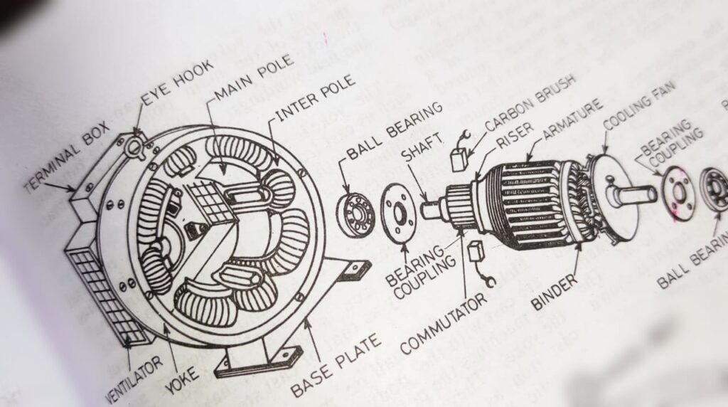
A dc motor is constructed with the following parts.
- Outer body or Yoke or Frame
- Field pole
- Field winding
- Field Shoe
- Interpole
- Armature or Rotor
- Commutator
- Brushes
Frame or Yoke or Outer body
It is the main part of a motor which made of generally cast iron and it’s shape is just like a cylinder and having two end cap also made of same metal to hold the armature. It holds the field pole and also make a magnetic ceiling for non leakage of magnetic lines of forces. As the cast iron is cheaper than other material normally cast iron is used for yoke.
Field Pole
It is that part of a dc motor which hold the field winding and made of thin sheets of laminated silicon steel. The number field pole is always in even number i.e 02 or 04 etc. The field coils are so connected in series in such a way that to produce opposite polarities at the adjacent poles. The function of these pole is to hold the the field coils and to produce magnetic field in the dc motor.
Field Winding
It is the vital parts of a dc motor that, it made with super enameled copper wire shaped as per the field pole and it produces the magnetic filed whenever it energized by dc external source.
Field Shoe
It is so designed to distribute magnetic lines of forces uniformly between the poles of dc motor.
Interpole
It is a supplementary pole which is placed between the main filed pole (90* electrically) and is connected in series with armature winding. It is used to neutralize the armature reaction. It’s polarity is same that of main filed pole to it’s precedes.
Armature or Rotor
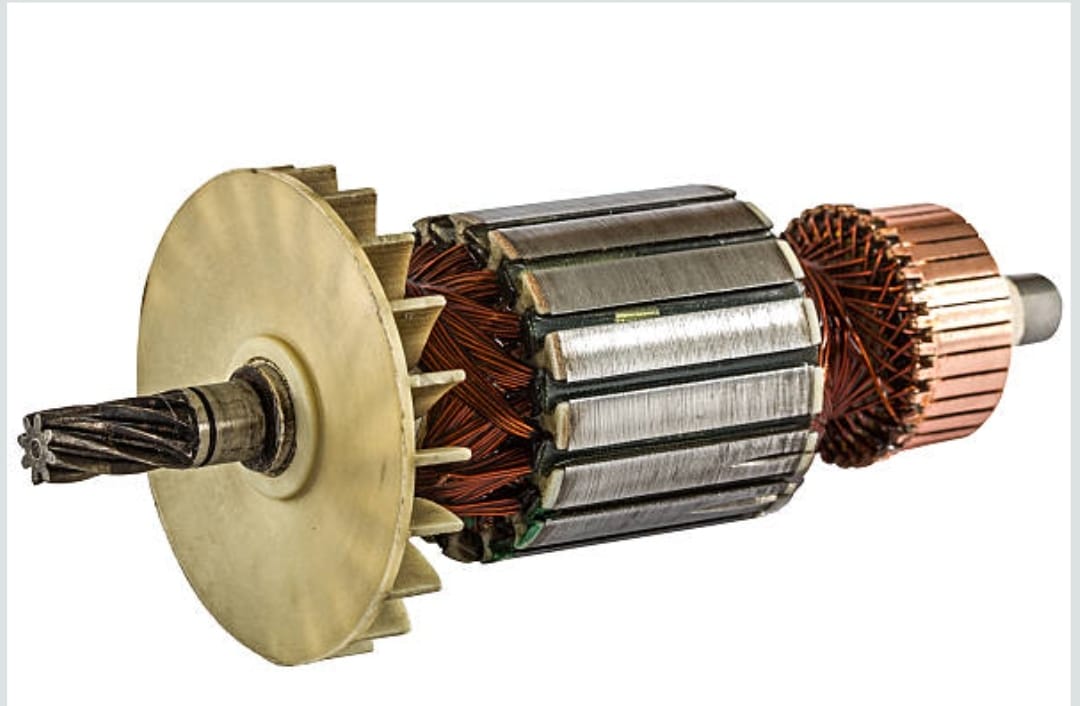
It is the rotating part of a dc motor, through which electrical supply is given to the machine. It is made of thin sheets of laminated silicon steel with cylinder shaped. It rotates about it’s axis and contains the armature winding in it’s slots. The armature is winded with copper conductor to produce the magnetic field which later interact with the main field winding then causes rotations of the armature or rotor of dc motor. One side of the armature is connected with commutator and another side is connected with a fan for cooling purpose as you seen in the above picture.
Commutator
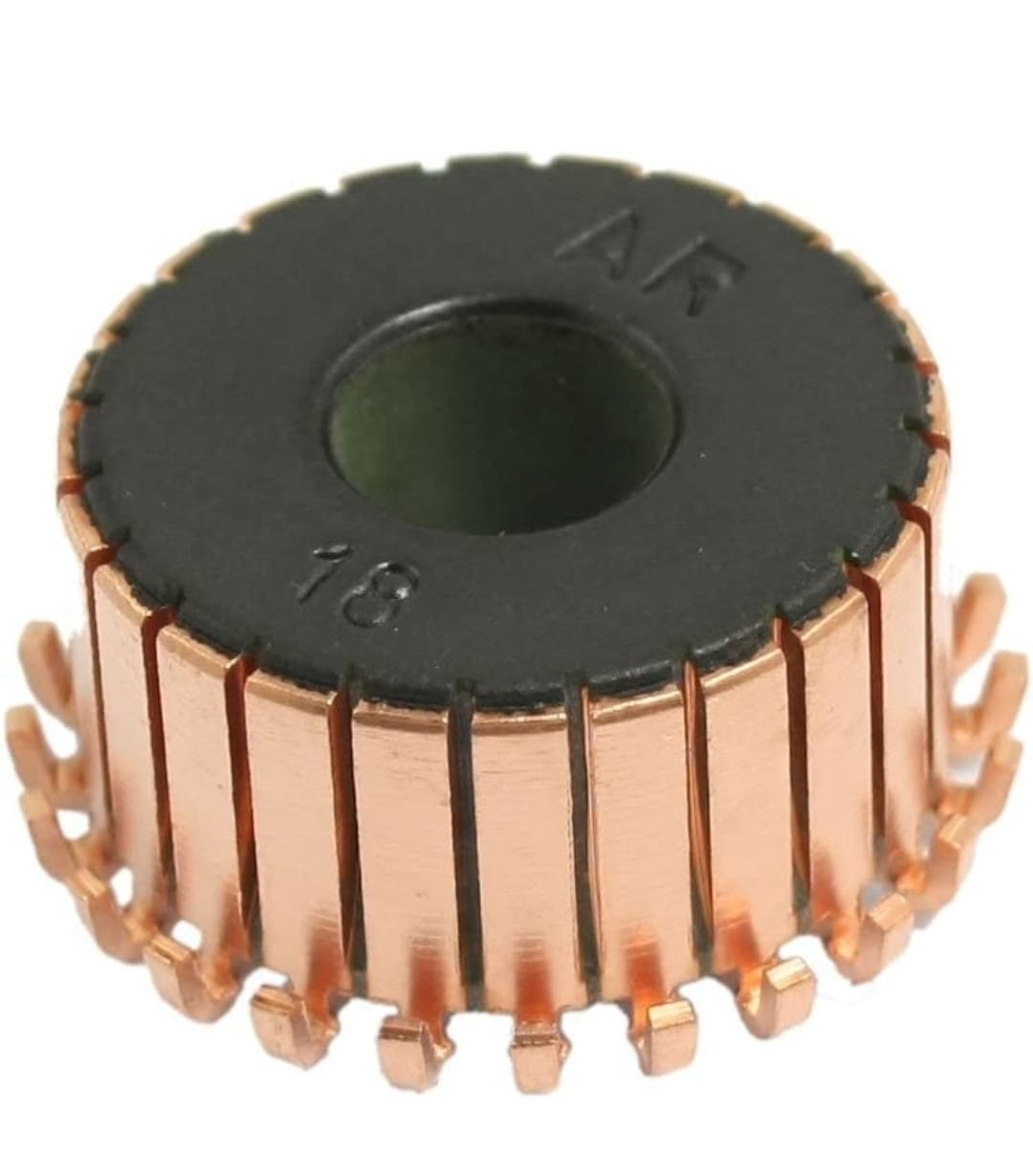
It is cylindrical in shape and consist of number of copper segments of high conductivity, hard drawn copper segments insulated from each other by means of mica. It’s main work is to reverse the current direction in the coil.
Brushes
It is made of carbon and rest on commutator against the spring tension. Through the carbon brush direct current is supplied to the armature.
Types of DC motor
There are three types of DC motor like
- Dc series motor
- Dc shunt motor
- Dc compound motor.
Dc Series motor
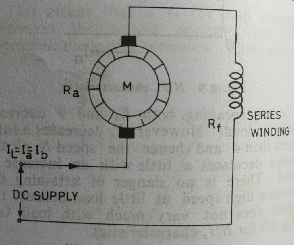
In the dc series motor the field winding is connected in series with armature. The series winding is of thick wire of few turns designed to carry the full load current as equal to the armature current. In this motor the line current is equal to the submission of armature current and series field current.
Application of dc series motor:- These motors have high starting torque on heavy load for which it is used in electric cranes, electric trains, hoists etc.
DC Shunt motor
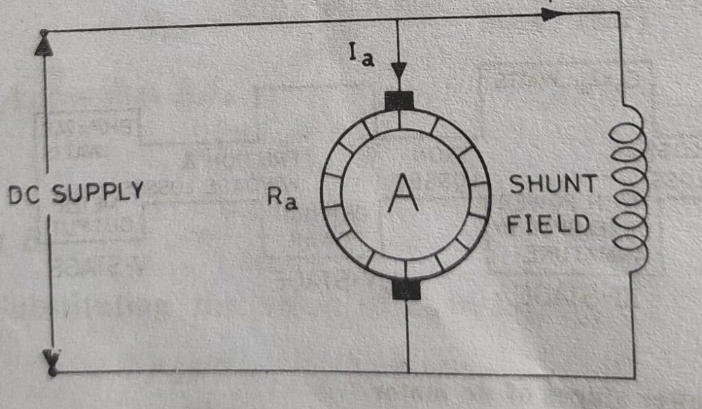
In dc shunt motor the field winding is connected in parallel to the armature and the full line voltage is applied to both armature and field winding. So the shunt field winding is of thin wire of many turns.
Application of dc shunt motor:- As the shunt field resistance is constant and applied voltage at the particular time is constant, the shunt field current is also constant and the field flux is also constant. So the speed of dc shunt motor will be constant. Due to constant speed characteristics this motor is used in leaths machine, saw mills, blowers, wood working machine etc.
DC compound motor
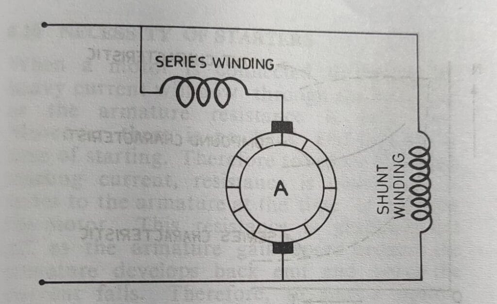
Dc compound motors are combination of dc series motor and dc shunt motor. This motor have one series winding connected in series with the field winding and one shunt field winding connected in parallel to the armature winding. The series filed winding is of thick wire of few turns and the shunt field winding is of thin wire of more turns. But in practical you can see that, the series field winding is wounded in the same pole of shunt field winding. The major portion of flux is produced by the shunt field winding.
Further this compound motor again divided in two types like,
- Differential compound motor
- Commulative compound motor
Differential compound motor
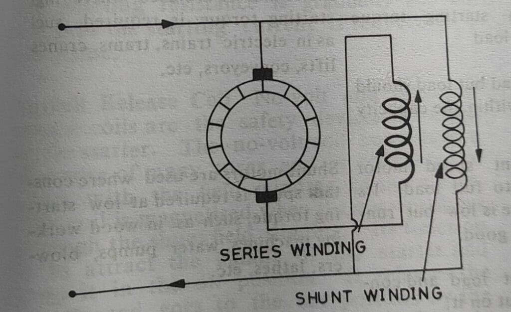
In this motor the field produced by the series filed winding is opposite to the field produced by the shunt field winding as shown in the above figure. The flow of current in both the field winding is opposite to each other. In the same pole if the series field winding produces the north pole then the shunt field winding produces the south pole. These motors are normally not used where heavy load is put on the motor.
Commulative compound motor
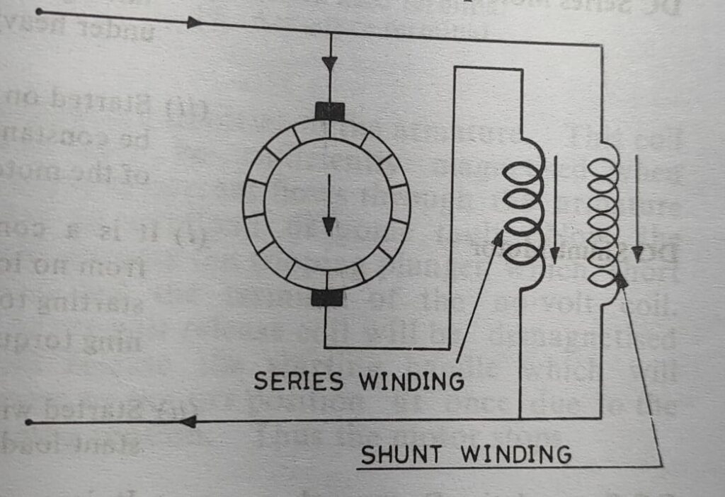
In this motor the series filed winding produces the flux which helps the shunt field flux. That means if the shunt filed winding is produces the north pole then series field winding is also produces the north pole. All the compound motors are normally commulative connected. When the load on this motor is increased the flux produced by the series field winding is also increased thus it results decrease in speed. However the decreasing speed is nominal as the major portion of fulx is produced by the shunt field winding. This motor has constant speed characteristics on different load.
Application of Dc commulative compound motor:- These motors are normally used where heavy load is suddenly put on the motor or put off . like elevators, rolling mills, punches, shears, heavy planners, conveyors etc.
Frequently asked question (FAQ)
What is Fleming’s left hand rule?
This rule is used to determine the direction of force acting on a current carrying conductor placed in a magnetic field. If the thumb, fore finger and middle finger of the left hand are stretched perpendicular to each other then the fore finger points the direction of magnetic field, the middle finger points to the direction of current flow then the thumb will point of the direction motion of the conductor.
What is back e.m.f ?
When the armature of a motor rotated in the magnetic field, it cuts the magnetic line of force and an emf is induced in it. This induced e.m.f opposes the applied e.m.f and therefore it is called opposing e.m.f or back e.m.f or counter e.m.f.
What will happen if d.c. series motor is started without load ?
Due to low field flux the motor will run at a very high speed which may cause harm to the motor and injury to the operator. (The speed is inversely proportional to the field flux).
What are the common methods of speed control of d.c motors ?
There are two common method for speed control i.e 1-Field control method and 2- Armature control method . In field control method more than normal speed can be achieved but in field control method speed only can be reduced with respect to its normal speed.

